Introduction
Reverse Osmosis is a superior technology to remove dissolved solids, pathogens from water by means of a semi-permeable membrane. Its ability to remove around 95% of the dissolved solids has forced industries to use this more than any other method. Despite its drawbacks, RO systems seem to have picked up over the last few years.
Osmosis vs. Reverse Osmosis
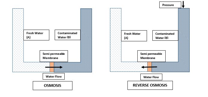
Osmosis is a generally occurring process where a low concentrated salt solution (A) will pass water molecules to a highly concentrated salt solution (B) when these two are separated by a semi-permeable membrane. Ideally, we want this to happen the other way around. Water molecules from a polluted water source to a pure water source are what people need. Sufficient pressure on the concentrated salt solution (B) can reverse the natural process. Applying energy by means of pressure forces water molecules to pass from B to A. The Pressure required to process this (Osmotic pressure) depends on the purity of the water source. Higher contaminant percentage higher the pressure required to pass water molecules through the membrane.
Industrial Usage of RO
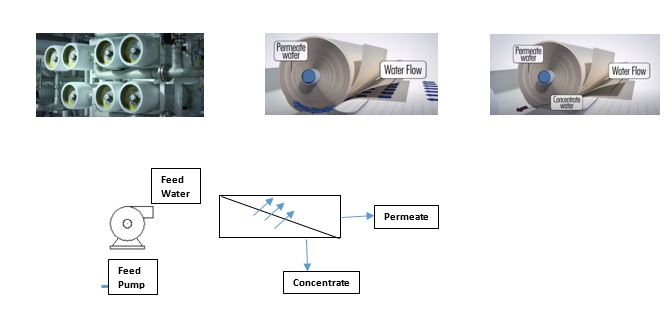
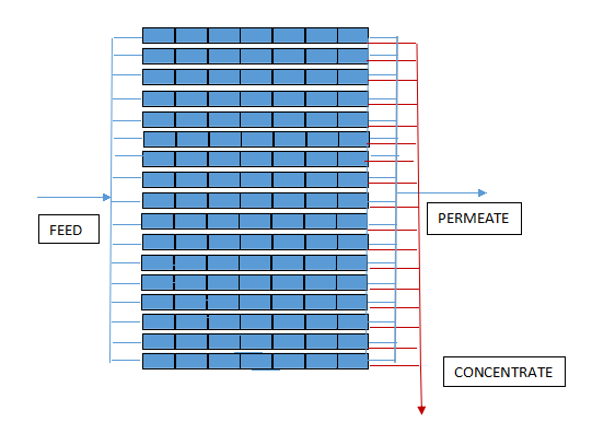
Concentrated water passes through circular RO membrane vessels. High-pressure feed pumps in the RO system overcome the osmotic pressure. As the saltwater (feed water) passes through the membranes, around 95 % of the dissolved solids get blocked by these hollow membranes. At the end of the vessel, demineralized water (Permeate) will come out from the perforated tube. Contaminated water that didn’t pass through the membranes (Concentrate) drains to a Wastewater treatment area for further treatment.
The ability to remove contaminants from a RO membrane depends on the size and the charge of the contaminants. The sizes of microorganisms are much larger than that of water molecules. Hence microorganisms will reject very easily through RO systems. Mono charged ions are unlikely to be removed through RO systems, whereas ions with 2 or more charges can be easily removed via this method. Reverse Osmosis doesn’t have the ability to remove Most of the Gaseous compounds in the feed water rejected through Reverse Osmosis systems.
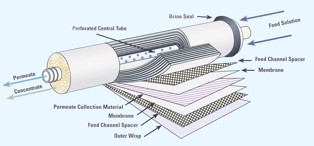
Reverse Osmosis Membrane
A RO membrane along with a feed spacer and a permeate collection layer is wounded around a perforated central tube, and then the whole set is covered with a fiber vessel. RO membrane consists of three layers in the form of a polyester layer, a polysulfide layer, and a thick polyamide barrier layer. Feed spacer allows the feed water to flow through the vessel, creating required turbulence to the process. Feedwater filtered through the membrane then directs to the permeate collection tube through permeate collection material.

Pretreatment
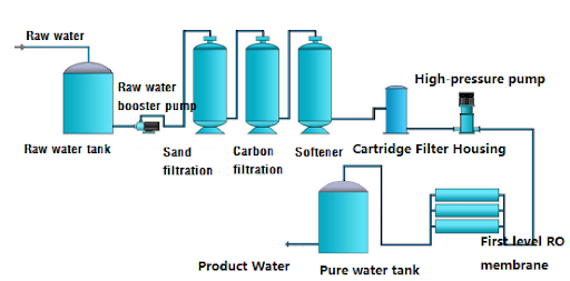
Often Reverse osmosis systems consist of a pre-treatment method. Damages to RO membranes can be costly. Scaling, fouling, and membrane damages by chlorine are some of the common issues. Ideally, feed water shouldn’t consist of suspended solids or microorganisms as they can block the membranes very easily. Using RO systems for the only purpose of removing dissolved solids can increase the duration of the membranes significantly. Hence a proper pre-treatment is a must. Raw water from a water source often goes through sand filters to remove suspended solids. Then goes through Activated Carbon filters or treated with Sodium Meta bi Sulfide to remove the free residual chlorine in the feed water. Then micron filters are placed to remove bacterias from the feed water. A pre-treatment method consisting of these processes has the ability to smoothen the Reverse osmosis process.

Chemical Treatment
RO membrane is the most important component in the system. Therefore it is vital to follow every possible step to protect these membranes. Antiscalants to inhibit scaling and Acids or Bases to correct the PH of the feed water should be dosed with close monitoring. Membrane cleaning processes can occur around 2-3 times a year. A low PH cleaner followed by a high PH cleaner is dosed (CIP chemicals) to remove any scaling or fouling that had occurred during the process.
Pros and Cons of Reverse Osmosis
Advantages
- Highly effective in removing Dissolved solids
- The only option for high purity water requirements
- Low maintenance costs
- Has the ability to remove even microorganisms
Disadvantages
- Produces a high amount of concentrate
- Power consumption is high
- Regular monitoring should be carried out
- The initial cost for RO systems are bit high
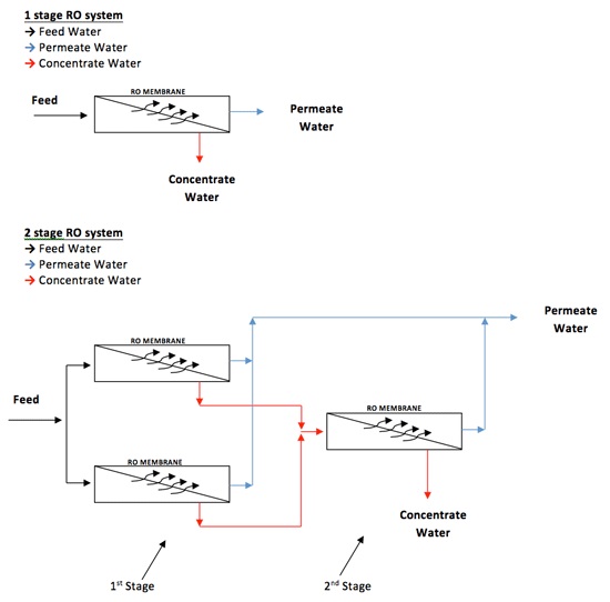
RO configurations (Arrays)
Single-stage RO systems and two-stage RO systems are commonly used in industries. A pressure vessel can contain up to 6- 8 membranes in it. In a single-stage RO, feed water will enter the pressure vessel, and at the end of the treatment process, permeate leaves the vessel while the concentrate dispose without further treatment. This method is common in areas where the water isn’t scarce. In a two-stage system concentrate that leaves the first stage passes to another RO systems as the feed. Permeate from both the systems are collected to a common header to be utilized in the processes. Increasing the number of stages can increase the recovery of the feed water to the system.
Design of a Reverse Osmosis System
Assume that these factors are given in a RO system
Water Source – Seawater
Feed Flow = 125 m3/hr
Recovery = 40 %
Permeate Flow = 125 *40%
= 50 m3/hr
Permeate flow = 220 GPM
Concentrate = Feed – Permeate
= 125 –50
= 75 m3/hr
Feed Total dissolved Solids = 30000 ppm
Silt Density Index = 6
- Feedwater source analysis is quite important in determining a suitable RO system. The recovery of the system has to be determined by a complete ion analysis. A suitable RO membrane should be selected considering the feed TDS and Permeate flow rate. Membrane suppliers’ catalogs will provide a complete set of details for the above parameters.
- Details required for the calculations from the membrane catalogs are maximum permeate flow rate and the Active surface area of the membrane. If the maximum permeate flow is higher than the system flow, and the membrane can treat the TDS limit of the feed water membrane can be utilized in the process. For the calculation purpose, we will assume the active surface area as 300 ft2
- Average Membrane flux has to be determined either by calculation or depending on the Silt Density Index of the feed.
| SDI | Average Membrane flux Gallons square foot per day (GFD) |
| SDI < 1 | 20-30 |
| SDI 1-2 | 14-20 |
| SDI 2-4 | 8-14 |
| SDI >4 | 7-8 |
Here the Average Membrane flux will be 7 GFD.
The next step would be to calculate the total number of elements (NOE) required.
NOE= Permeate Flow (GPD)/ (Average Flux (GFD)*Active Membrane Surface Area (ft 2))
= 316800 GPD/ (7 GFD * 400 ft2)
= 114 elements
- For smaller units, 1 ore 2 elements per pressure vessel are used mostly. The most common number of elements per vessel is 6, and this can go up to 8, considering the permeate flow rate. In the example, we will consider the number of elements per vessel as 7. Therefore the total number of Pressure vessels (NOP) can be calculated for the system.
NOP = NO of Total elements/ No of elements per vessel
= 114/7
= 17 (rounded)
- The number of stages can be determined depending on the recovery rate.
| Recovery Rate | Number of stages (For 6 element vessels) (Brackish Water) |
| 40-60 | 1 |
| 70- 80 | 2 |
| 80 -90 | 3 |
| Recovery Rate | Number of stages (For 6 element vessels) ( Sea Water) | Number of stages (For 7 element vessels) (Sea Water) | Number of stages (For 7 element vessels) (Sea Water) |
| 35-40 | 1 | 1 | – |
| 45 | 2 | 1 | 1 |
| 50 | 2 | 2 | 1 |
| 55-60 | 2 | 2 | – |
Here the recovery rate is 40%, and the feed water comes from the seawater. Hence the number of stages will be the array of the Ro system is the total arrangement of the pressure vessels in the system in all the remaining stages. Since there is a single-stage in the example, all 17 pressure vessels are being placed in parallel.
Pingback: Why Boiler Water Treatment is Required - ARHSE - Chemical Engineering